The
invention
- The
problem to be solved:
The
main aim was to design an
internal-combustion engine that does not
contain components having alternate
longitudinal motion and directly converts
the fuel heat energy into rotational
motion with a high efficiency.
|
- Definition:
The invented
internal-combustion engine uses two
rotary vane pairs in the cylinder instead
of an alternate longitudinal motion
piston and, this way, four varying volume
regions are obtained. The vane pairs
alternately turn in the same direction
after each half turn due to the forced
coupling between the two vane pairs.
There is an approximately 60 degrees
segment when both vane pairs are turning
together in the same direction. This
arrangement realises the four stroke
tasks (aspiration, compression,
explosion, exhaust) required for the
operation. It is a valveless engine.
|
- Presentation:
The engine cylinder is
divided into four varying volume regions
by four vanes (two vane pairs) and the
vane pairs are rotated alternately. Each
vane pair makes a half turn and there is
an approximately 60 degrees segment where
they turn together near the dead point
position and when the two vane pairs
become closed to each other. The
operation of the engine can easily be
understood on the basis of the attached
schematic diagram that shows the inner
layout of the cylinder with the vane
pairs. The vanes isolate the regions from
each other. No valves used due to the
novel design.Legend: (1) is the
cylinder block, (2) is the aspiration
inlet, (3) is the exhaust outlet, (4) is
the spark-plug, (O) is the centre of
gyration, (A) and (B) are the two vane
pairs in the figure.
The
figure shows the position of vane pair
(A) just after the moment of explosion
and it is turning counter-clockwise.
There are four isolated regions formed
between the four vanes. As can be seen in
the figure, in the four region the
following tasks are performed on the
effect of and after the explosion: an
exhaust, an aspiration and a compression
occurs continuously. During this phase
the vane pair (B) is blocked with respect
to the cylinder block and does not move.
After a 120 degrees turn of the vane pair
(A) vane pair (B) starts to turn together
with the vane pair (A) in the same
direction. After a half turn vane pair
(A) stops. The same condition is repeated
in case of vane pair (B) and vice versa.
The alternate operation of the vane pairs
are controlled mechanically by a
synchronously rotating forced coupling
that is not shown in the attached figure
due to the limited space available.

Fig. 1. Inner layout of
the cylinder with the vane pairs.
|
- Application:
The invented engine can
be used in the same fields where the
traditional internal-combustion engines
were used, specially there, where a
highly reduced vibration, smoothly
operating and economical petrol engine
required.
|
- Advantages:
The
vibration is highly reduced because it
does not contain traditional piston nor
other components that have an alternate
longitudinal motion. Its construction and
operation are simple, since, no valves
nor valve gear required. Its weight and
dimensions are twice as low and small,
respectively, its turning moment is
approximately twice as high as those ones
of a four-stroke Otto-engine having the
same displacement volume.
|
- Stage
of development:
No
prototype has been built as yet, due to
the limited economic situation, but a
demonstration model is available which
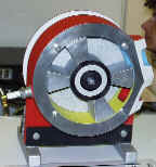
verifies the concept that it can
technically be realised and it really
works.
|
- Documentation
available: Yes
|
The
inventor(s)
- Self
introduction: The inventor is
37 years old, Hungarian citizen. He is a
skilled worker, a car mechanic. He has a
wide sphere of interests, specially, his
favourite field of interest is the
mechanics. He is fond of the novelties
and he himself searches also for the
unusual solutions.
|
The
protection
- Form:
patented (registration
no.: 217 342)
- Priority: 1994/1999
- Countries
where it is force: Hungary.
|
Business
intention: The inventor is looking for an
investment partner who could cover the costs of
further development and the manufacture of the
engine and, who could facilitate its introduction
to the market.
|
Contact
- Name:
Attila PÁSTI
- E-mail:
bpasti@freemail.hu
- Fax:
- Phone:
+36-42 490-768
- Address:
H-4400
Nyíregyháza-Kőlapos, Korhány út 12.
Hungary
|